2-element delta loop antenna for 6m band
published:
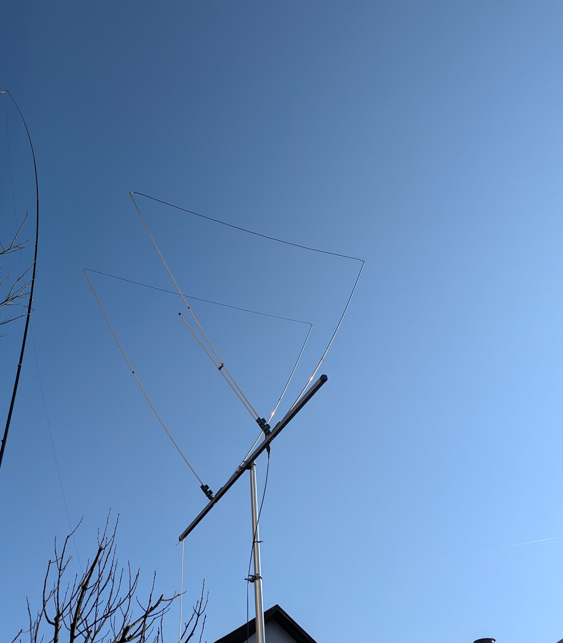
I did not yet have an antenna for the 6m band, so I decided to make a 2-element delta loop.
The mechanical design described here is the final design, which otherwise went through more than 3 iterations after a lot of review feedback received from fellow senior HAMs from my local radioclub, for which I am very grateful.
Electrical design
- Driven and reflector elements: closed loops, electrically connected to the boom
- Connector mounted directly to the boom
- Feed point at the lower apex, impedance matching using a gamma match
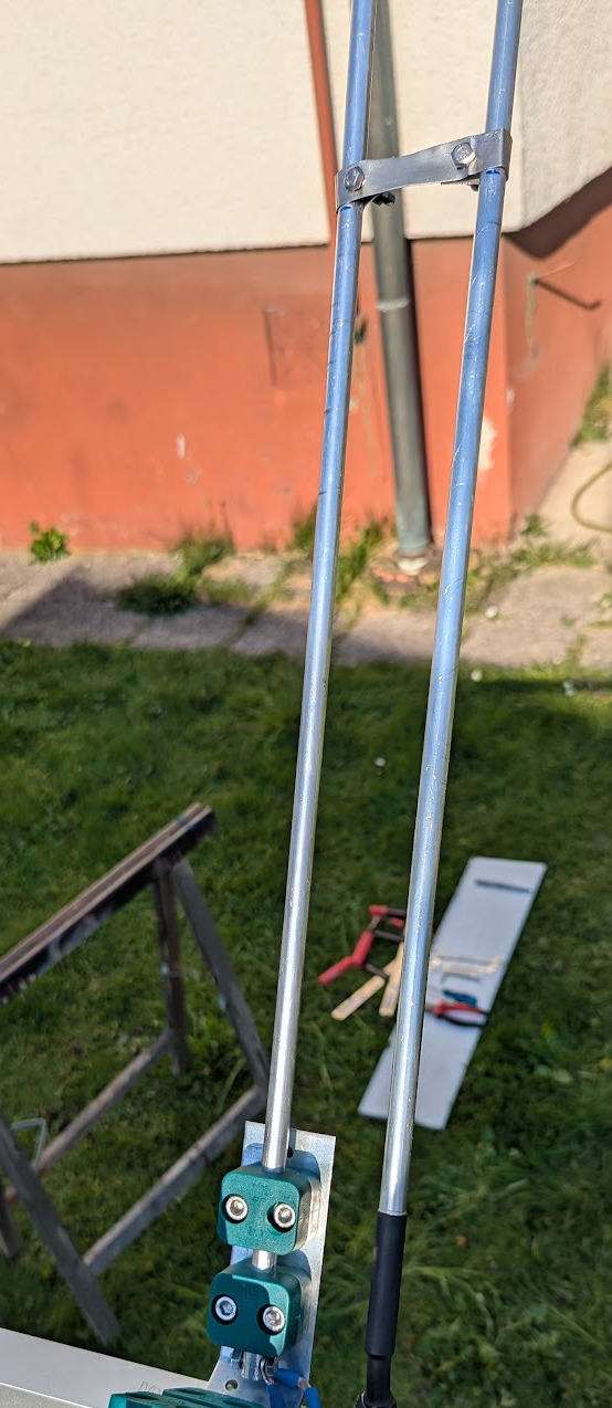
- Left and right legs of the loop: aluminum tubes, Ø 10 mm, wall thickness 2 mm (providing sufficient mechanical strength)
- Top leg of the loop: soft insulated wire, 6 mm²
- Spacing between driven element and reflector element: 0.14 lambda
- Element dimensions approx. starting points (before tuning):
- Driven element loop: 597 cm (2x196 cm legs + 205 cm top)
- Reflector element loop: 3% longer than the driven element: 615 cm (2x200 cm legs + 215 cm top)
This was the initial electrical design. Then, during antenna tuning (target resonant frequency adjustment), I was adjusting the length of the top leg (the wire) accordingly.
Mechanical design
- Boom: square aluminum tube 25 × 25 mm, wall thickness 2 mm
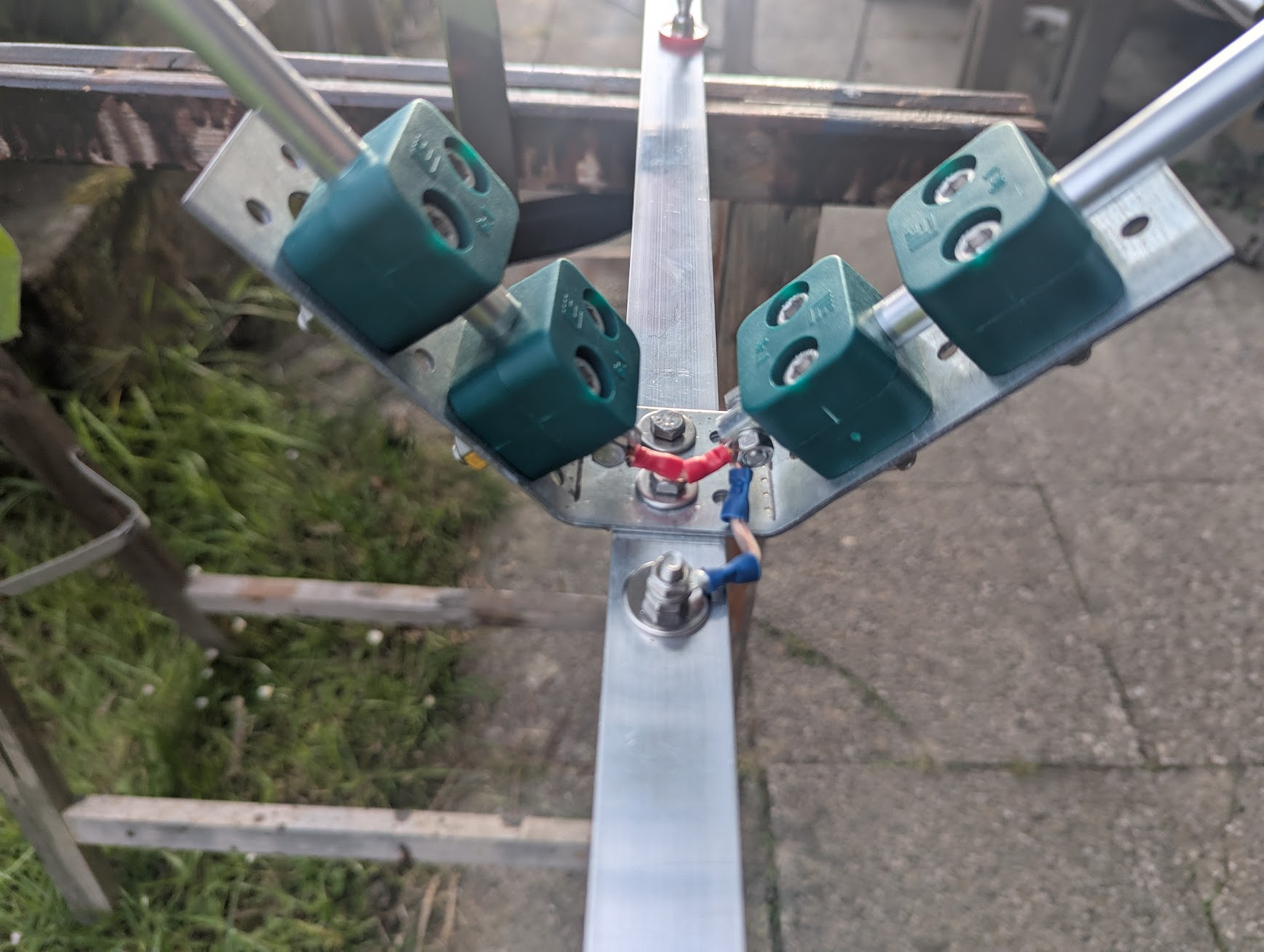
- Elements mounted on a manually-bent metal angle bracket with a horizontal section for mounting to the boom
- Elements attached using DIN 3015 clamps (Kovinoplast Laharnar)
- The V-support angle bracket has approx. 90-degree angle (and not 180/3 = 60 degrees), which causes both aluminum tubes to bend slightly, making the wire and the entire structure more tensioned and thus more stable
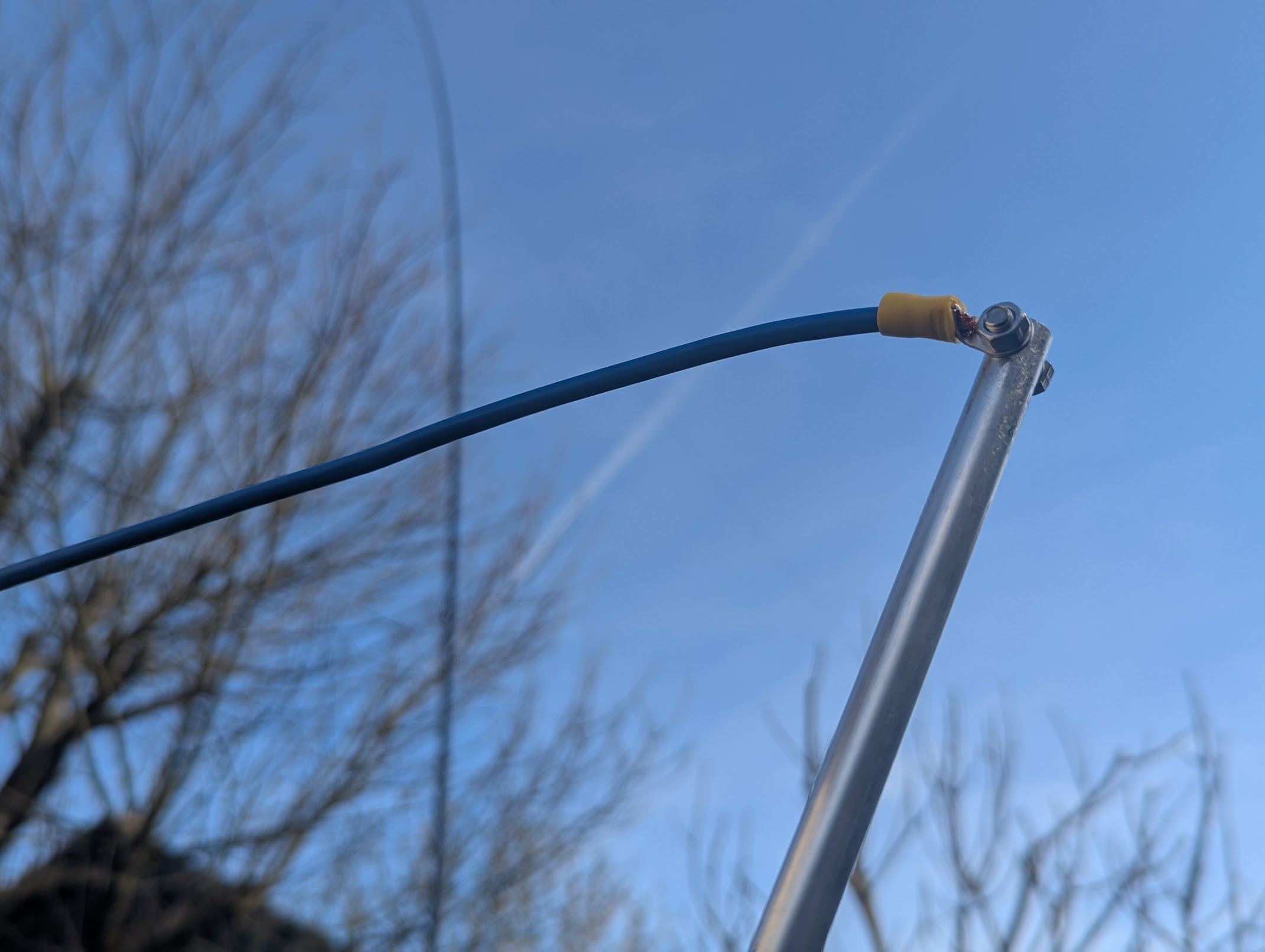
- All copper-to-aluminum connections made via cable lugs
- On the bottom side of the boom, small vent consisting of two holes Ø 3 mm
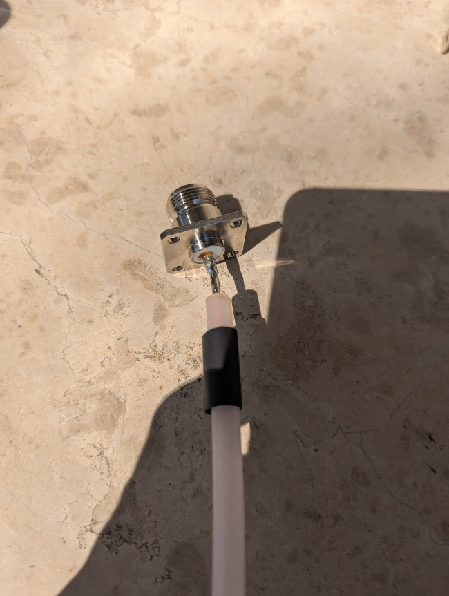
- N connector mounted directly to the underside of the boom (The outer shield of the coaxial cable is therefore electrically connected via the connector housing directly to the bottom center point of the loop.)
- screwed only into the bottom wall using self-tapping screws
Gamma match
- The N-connector housing is electrically connected to the boom; the hot center conductor of the cable (with dielectric) exits at the top
- The Gamma match capacitor is made from an aluminum tube slid over the center conductor of the coaxial cable together with its dielectric
(RG213 with the outer insulation and shield removed) - Gamma tube: aluminum tube with 10 mm outer diameter and 1 mm wall thickness
(inner diameter thus 8 mm, suitable for the RG213 center conductor with dielectric, diameter 7.25 mm) - Hole on the top side for passing the hot conductor with dielectric: to make everything as tight as possible, drilled first with a smaller drill (7 mm), then gradually enlarged with a file until the insulation could be pushed through with some resistance
- Gamma shorting bar: an aluminum plate cut into a rectangular strip, bent appropriately, and drilled for mounting screws
Driven element connection to boom. Not yet in the picture: After tuning, I sealed the lower part of the gamma match with adhesive-lined heat-shrink tubing.
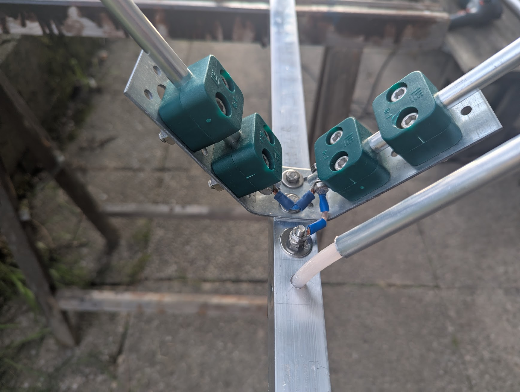
Driven element, bottom view, N-connector, gamma match tube:
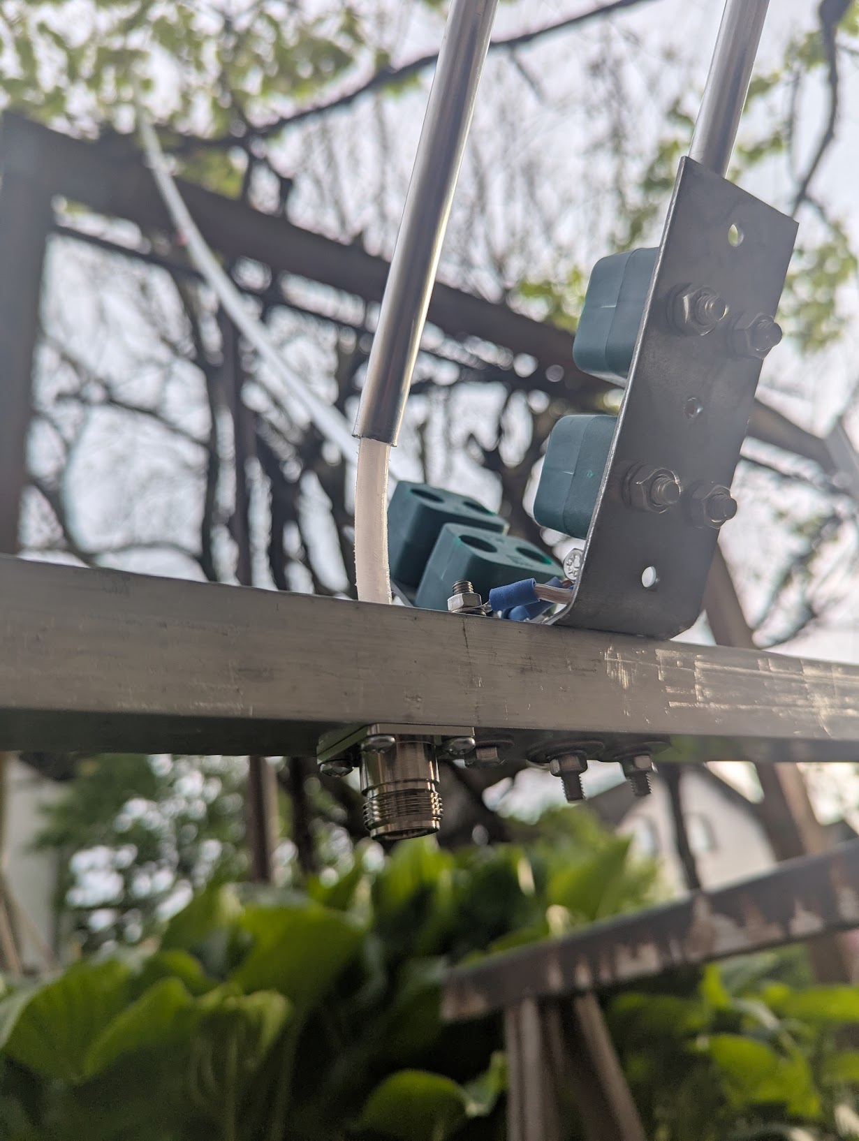
Reflector element connection to the boom:
N-connector soldered to the center conductor of RG213 with outer insulation and shield removed (picture taken before sealing with heat-shrink tube):
Connections of copper wire to aluminum tube elements via cable lugs:
Gamma match shorting bar:
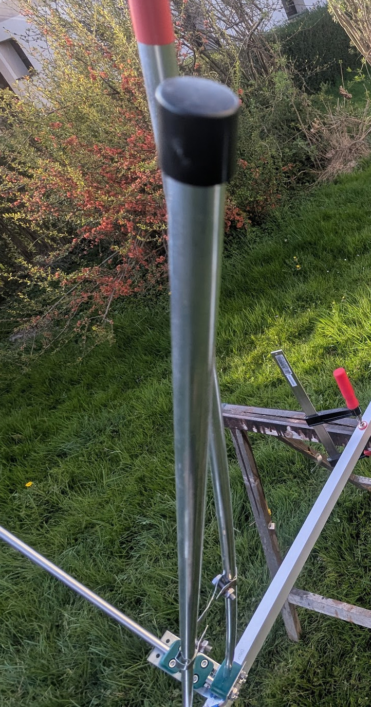
The gamma match tube sealed at the top with a plastic cap (Plastika Bevc):
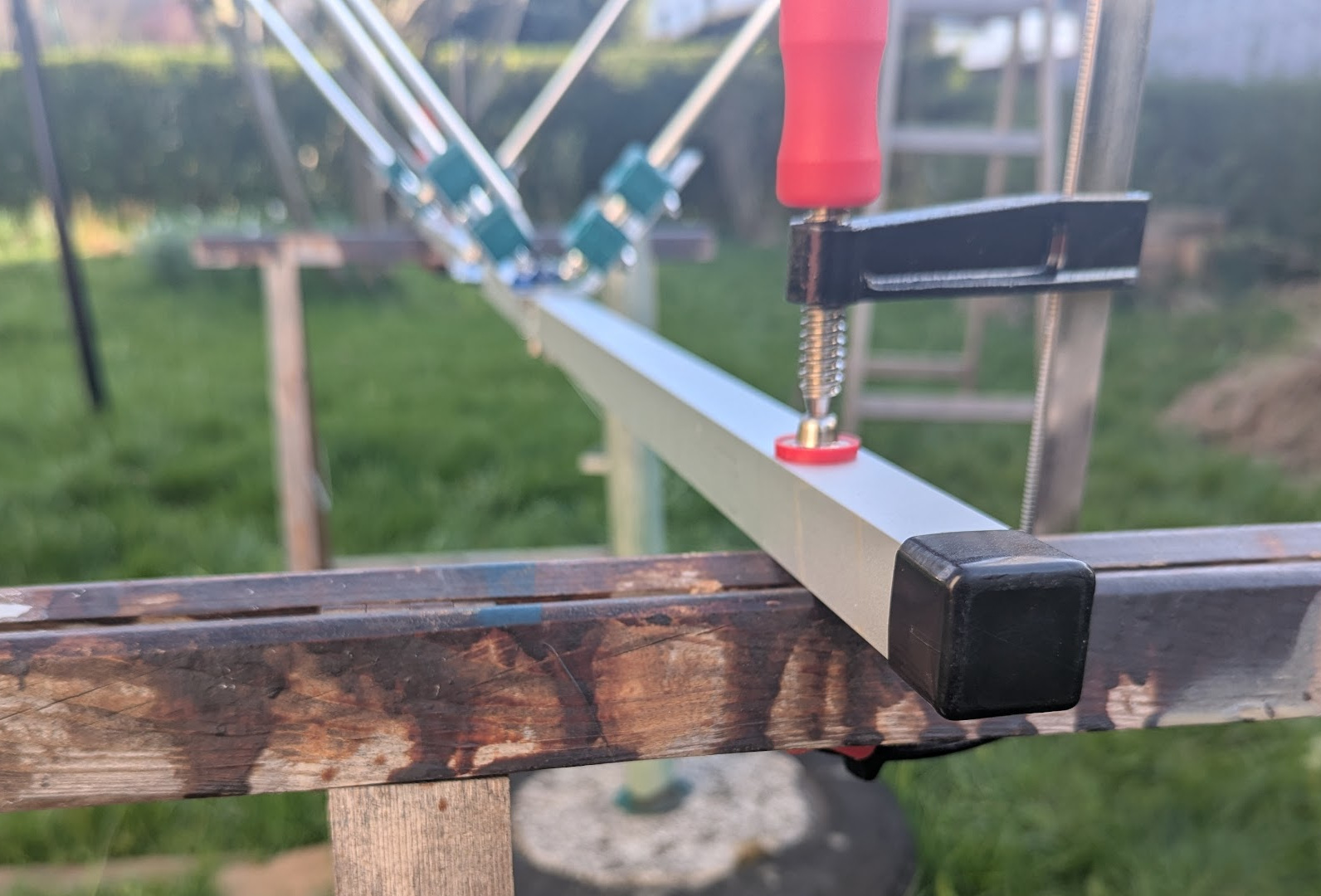
Both Ends of the boom tube sealed with plastic caps (Plastika Bevc):
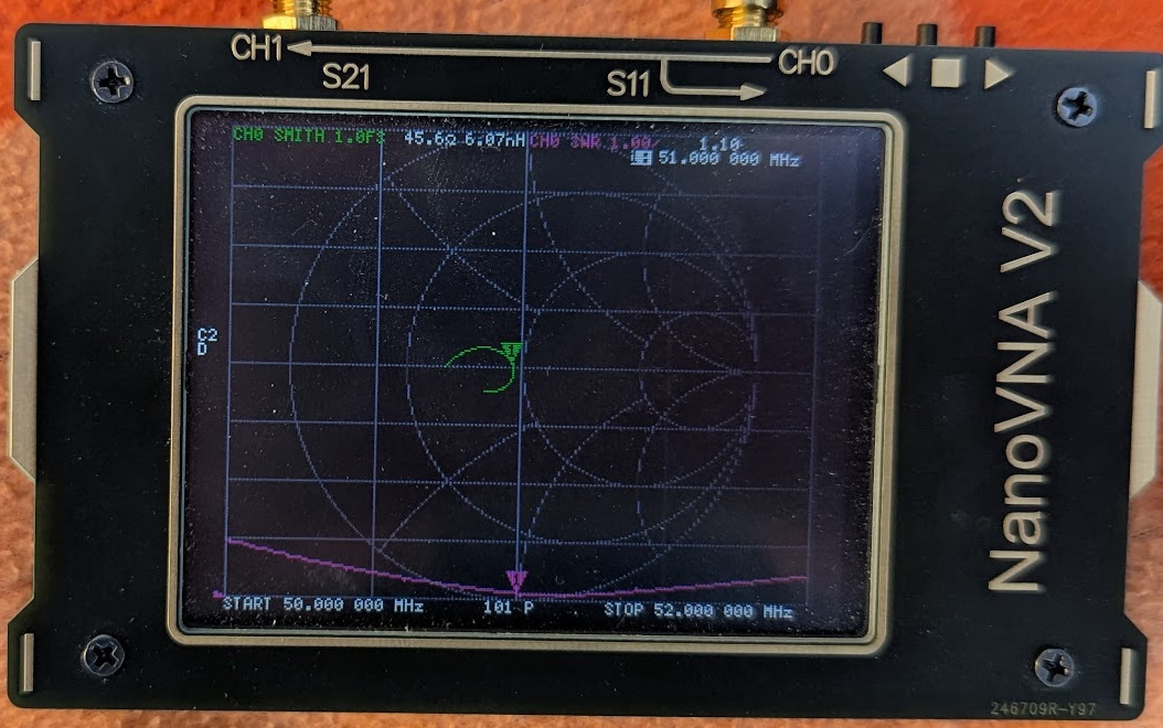
Final SWR/smith after tuning. Was targeting the center of the band (51 MHz), only later I realised it would be a bit better to target the lower portion of the band which is used more (CW, SSB, digi).