DIY 5-element 70cm yagi antenna
published:
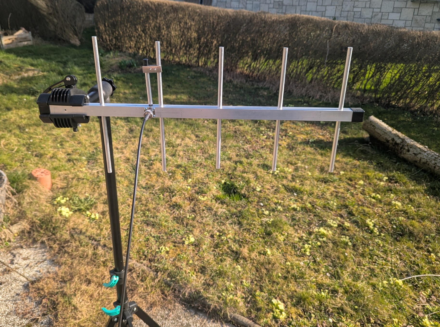
I constructed my first Yagi antenna — a 5-element Yagi for the 70 cm band.
I could have picked an existing, well-proven design somewhere from the internet and followed it as accurately as possible. Instead, I decided to try my own (simple) design and also model it beforehand using EZNEC, I found that to be more exciting and interesting for my first yagi build.
Electrical design
Traditional, simple principles:
- Driven element: Approx. 0.5 wavelength
- Reflector element: 5% longer than the driven element
- Director elements: all directors of the same length, 5% shorter than the driven element
- Spacing between all elements: equal spacing of 0.2 wavelength
I don't expect such a simple approach would match professional antenna designs (which may be calculated using expensive modeling software, fully optimized, often with varying spacings between elements, and directors of different lengths). Still, let’s give it a try and see how well it works.
Below is my simplified EZNEC model for the Yagi with a center frequency of 434 MHz (later I targeted roughly half a megahertz lower). The model is approximate — for example, it does not take into account the metal boom or the fact that the elements are electrically connected to it. It also does not model impedance matching.
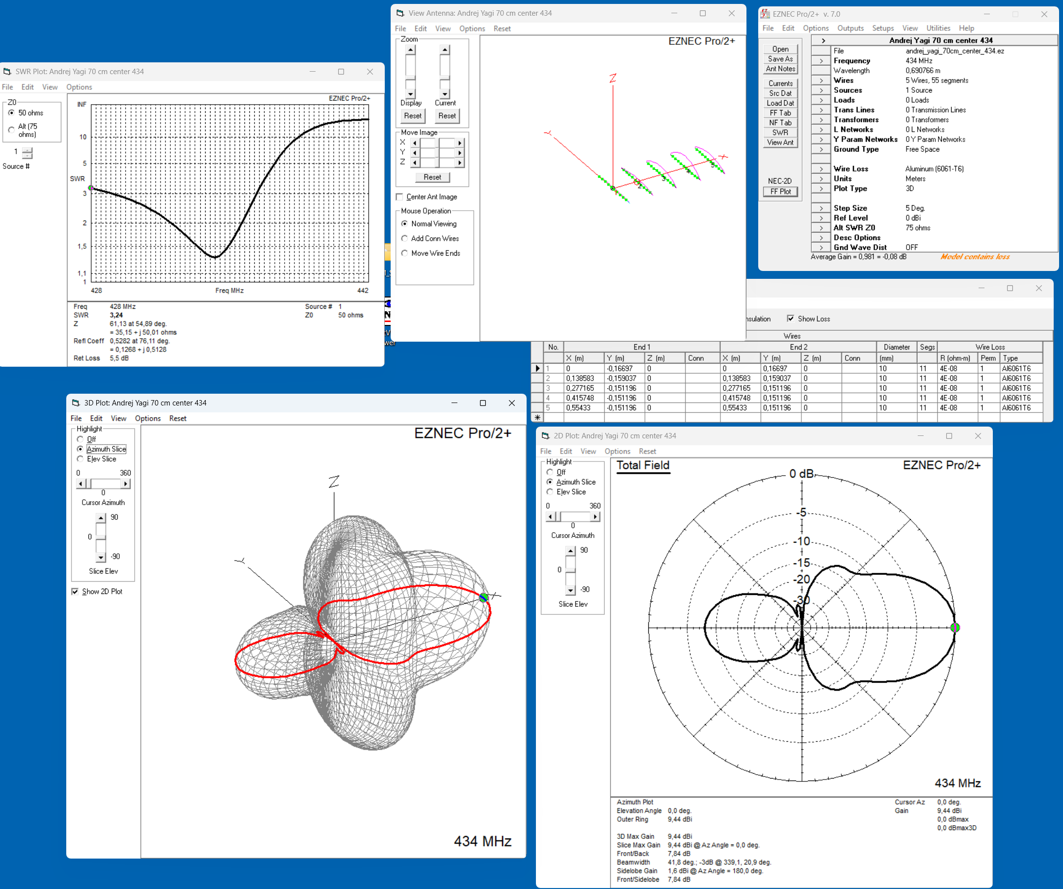
The EZNEC model based on this principle already looks quite decent, at least to me.
Mechanical design
- Elements: aluminum tubes, Ø 10 mm
- Boom: square aluminum tube, 25 × 25 mm
- Elements pass directly through the boom and are electrically connected to it
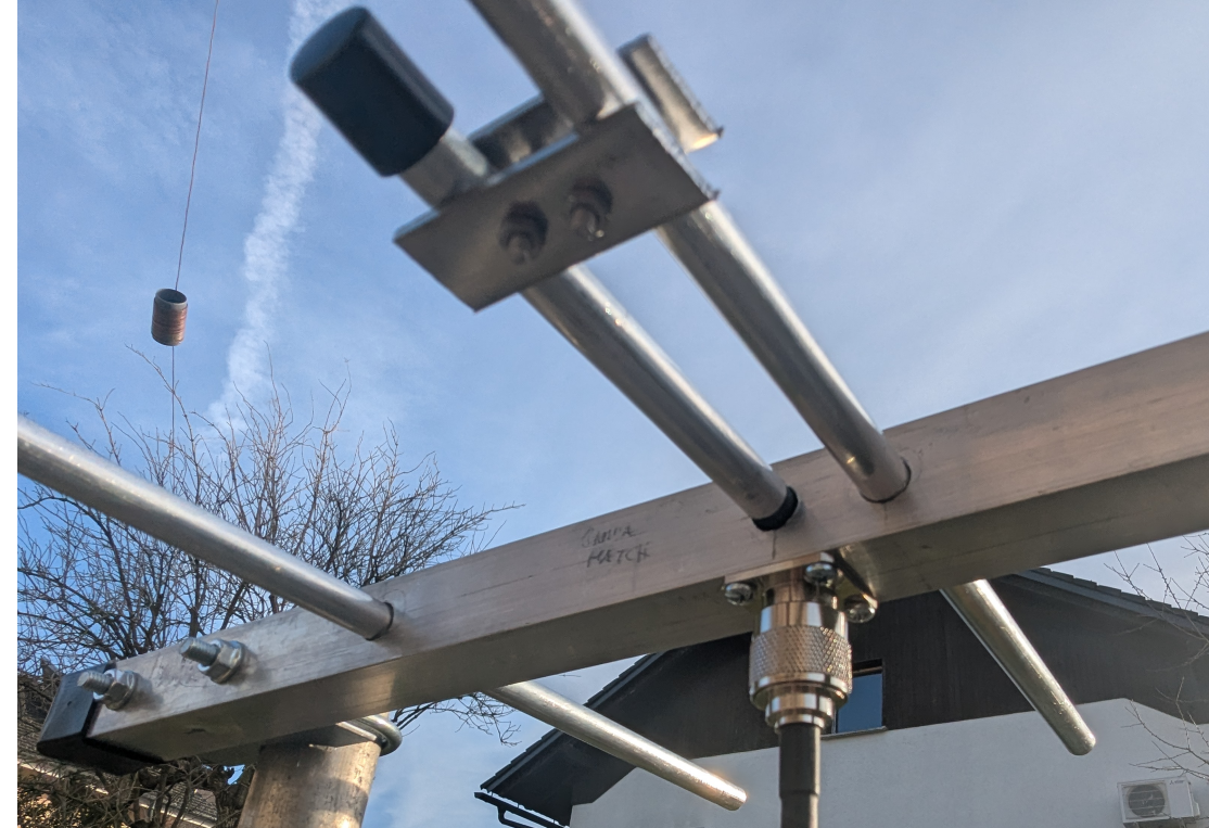
- Gamma match
- N connector
- Connector and elements secured with self-tapping screws
- Vent hole at the bottom: Ø 3 mm
- Gamma-match shorting bar: from stainless-steel square profile
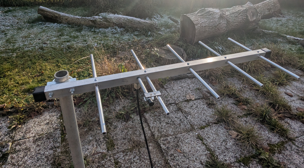
Of course I started with element lengths that were significantly longer than those predicted by EZNEC and shortened them gradually. In the end, to my surprise it turned out that my EZNEC simplified model was quite accurate. The final physical dimensions were less than two millimeters shorter than the EZNEC-calculated values. Hmm, interesting, not sure why I expected bigger deviation.
Final values:
- reflector: 33.3 cm
- driven element: 31.7 cm
- directors: 30.0 cm
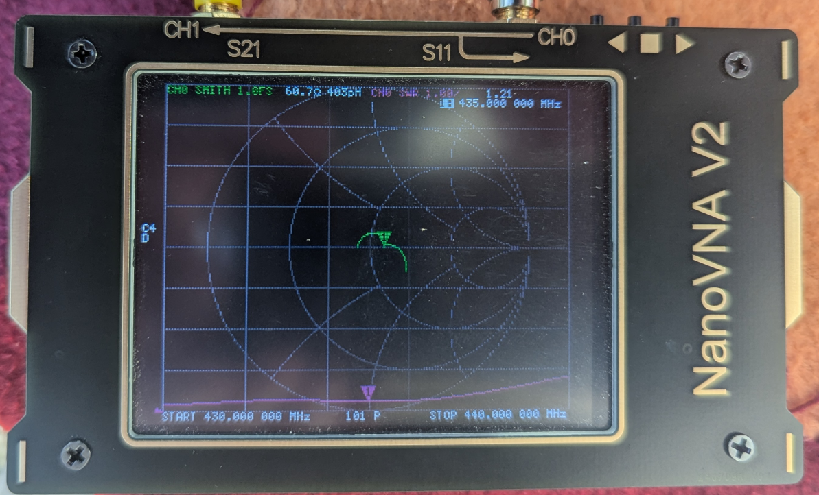
Bandwidth: fairly wide. SWR below 1:2 the whole range 430 to 440 MHz. The lowest SWR was around 1:1.21 in a horizontal setup on a metal stand. I was not able to achieve 1:1 with this gamma match in that configuration (I suspect I may have cut too small of a section of the RG213 center conductor with dielectric and was lacking capacitance). Interesting or not, when holding the antenna in my hand, the SWR did reach 1:1 at one point.
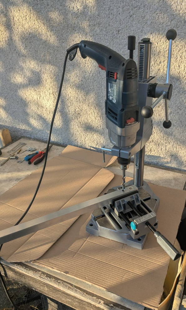
I have upgraded my life: Finally bought a drill stand. (an entry-level one)
To possibly improve
- Seal the gamma tube at the bottom with heat-shrink tubing
- Seal the ends of the elements with plastic caps
- The mast mounting clamp should better be oriented for vertical polarization, which will be more commonly used on this band